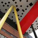
Stars + Steel: OCAD
Construction and Erection: Sitework + Preparation
The addition involved the preparation of the existing OCAD courtyard to accept the concrete stair and elevator core as well as casting the caissons that would provide support for the legs.
Images: PCL Constructors
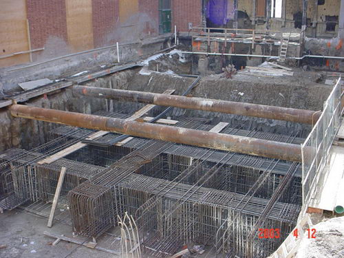 |
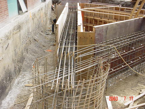
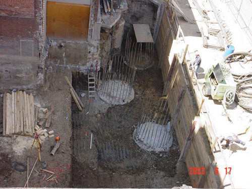
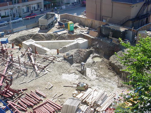
As the courtyard was situated directly adjacent to the existing school building that had to remain intact and operational throughout construction, care had to be taken not to damage the existing structure. Here we can see the use of round HSS as crosslot type bracing to allow for the excavation of the courtyard. |
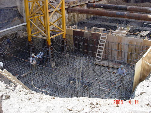 |
The reinforcing bars are installed for the deep raft slab type foundation under the new core. You can see how the rebar for the yellow crane tower has been worked into the situation. |
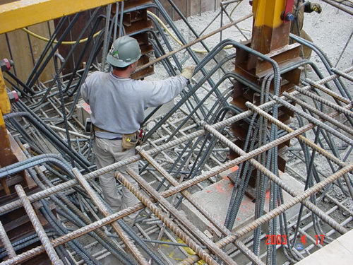 |
A closer view of the base of one of the legs of the tower crane structure and the amount of rebar that is being used in the slab. |
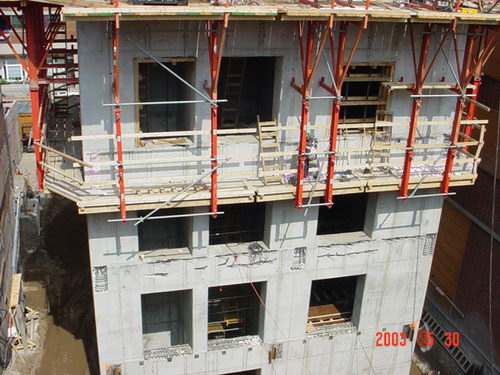 |
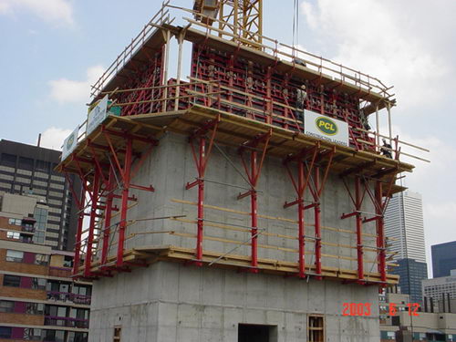
The concrete core proceeds first as it will be used to allow for the erection of the table top trusses. |
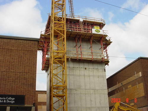 |
The table top will sit above the existing school building so the construction of the core must be fairly complete before the erection of the table top trusses can begin. |
 |
A closer view of the formwork that is used on the central core. |
 |
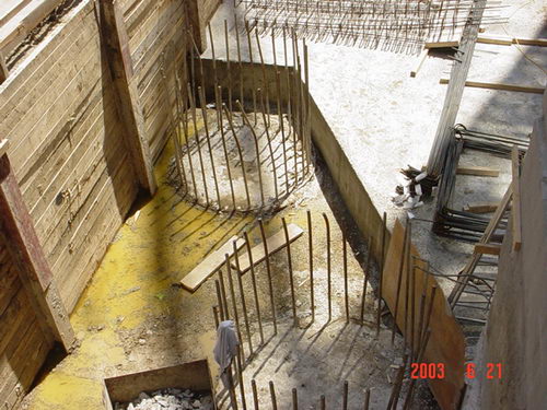
A view of the steel reinforcing inside of the caissons. Although there are only two legs at each foundation point, the caissons have been constructed in "threes" as a means to add stability to the sloping legs and as part of the seismic design for the project. |
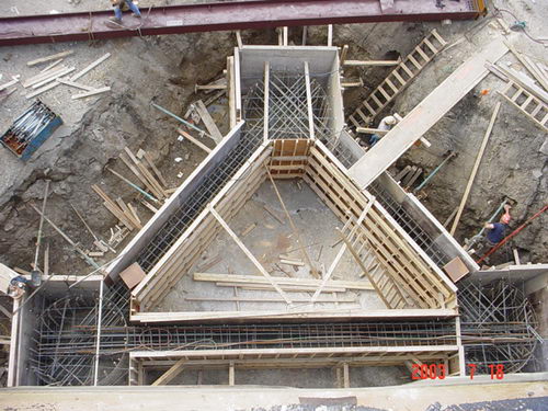 |
A view down onto the foundations for a pair of legs. |
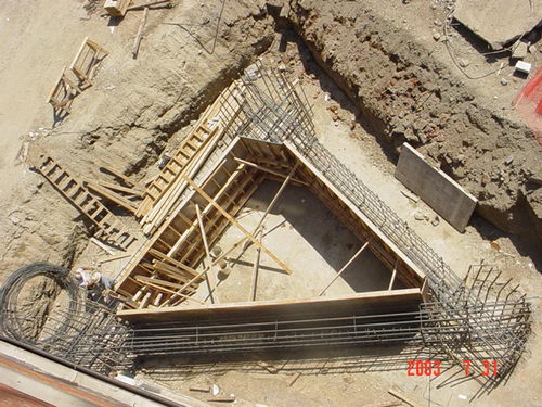 |
A view down onto the foundations for a pair of legs. |
 |
Once the foundations are completed the formwork is removed and they are backfilled. |
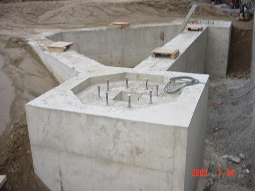 |
A view of the caisson foundation top after the removal of the formwork. Make note of the square hole in the recess of the top of the foundation as well as the octagonal depression. This has been formed to rather precisely accept the steel leg. This part of the foundation is poured on top of the caissons. |
 |
A view down onto some of the caisson tops that sit beneath the structure illustrated directly above. |
 |
A view towards the foundations for the south east pair of legs. |
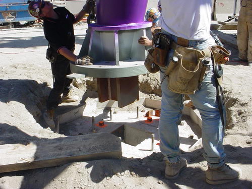 |
Here you can see how the base of the column fits into the key depression at the top of the caisson cap. The threaded bolts that are set into the cap must align with the holes in the base plate of the column. |