Stars + Steel: OCAD
Engineering Drawings
The Engineering drawings below depict the foundation plan, fifth floor plan, elevation of the major trusses, and detail of the fire stair.
 |
|
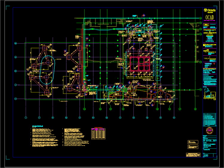
| FOUNDATION PLAN - showing the location of the caissons that support the legs. Note that there are 3 caissons per each pair of legs. This was to give added stability due to the seismic location. | |
 |
|
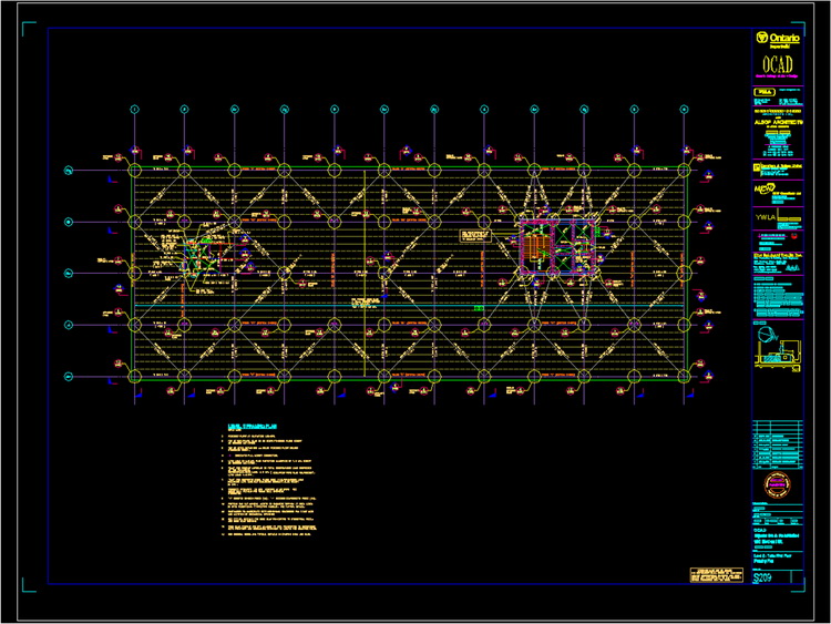
| FIFTH FLOOR PLAN - The fifth and sixth floors are quite similar. The plans show the offset location of the core. | |
 |
|
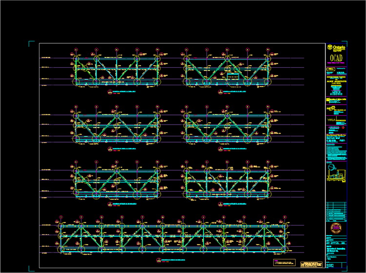
| TRUSSES - This drawing shows the elevational views of all of the major trusses. Some of these needed to be broken into sub components for purposes of shipping and erection. | |
 |
|
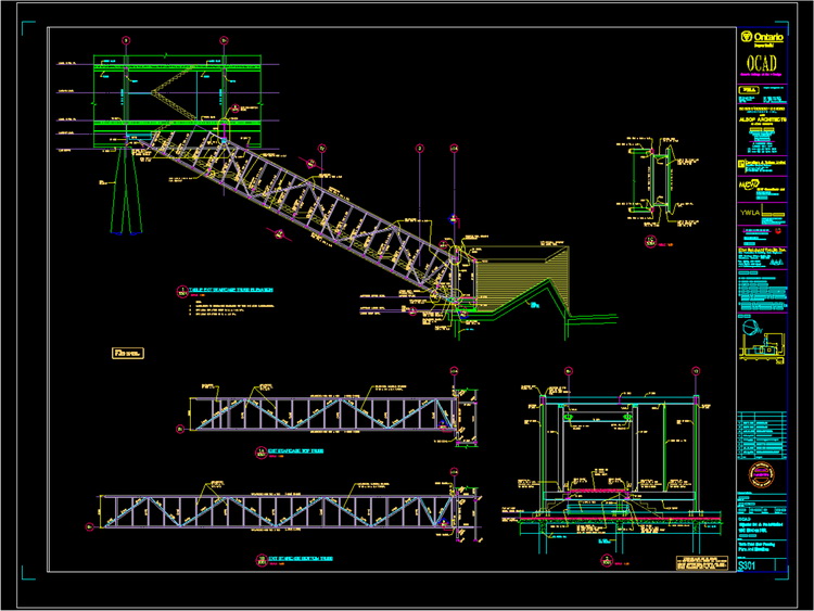
| EXIT STAIR -The main exit stair from the far end of the table top was a critical element in the fire protection scheme as it was critical in providing a second means of egress from the south end of the building. | |
 |
|
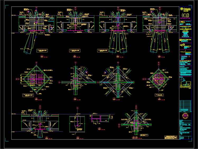
| DETAILS - This is a sheet showing some of the key details for the project. Of particular interest were the connections between the AESS legs and the concealed steel frame at the underside of the table top. | |