Innovative Connections
Steel and Glass
New technological developments have both increased the options available and reduced the difficulties in designing, detailing and erecting AESS steel and glass buildings.
There are three basic ways to consider the way that steel acts as a support system for expansive glazed applications:
• The steel framework is used simultaneously as the structure and the method of holding the glass in place, whereby the glass is virtually in the same plane as the steel.
• Larger steel members are used directly behind (or in front of) the glass system to provide wind bracing; these members can be installed vertically or horizontally at the mullions and usually do not also support the floor loads above; structural steel sections, trusses or cable systems are used.
• The steel structure sits back from the glass to provide the lateral support and creates a separate, unique structure of its own; an interstitial support system (often cables) is used to connect the glass to the steel.
Tempered glass is most commonly used in these applications. Glass is tempered by heating it to 650-to-700 degrees C and rapidly cooling it so the centre retains a higher temperature than the surface. As the centre cools, the resulting contracting induces compressive stresses at the surface and tensile stresses in the core which can produce a pane of glass four or five times stronger than annealed or float glass. Protection against breakage can be enhanced by laminated units where multiple layers of glass are bonded by a layer of plastic sheet material. The combination of different layers improves post-breakage behaviour of the glass and gives designers and building owners more confidence to use it in larger applications.
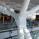
Many AESS and glass structures are designed as signature elements of the building. The steel interface elements of these signature structures transfer portions of the wind loads to the steel superstructure, hence the interface elements are generally small but a much higher emphasis is placed on their visual appeal. The steel fabricator retained must be familiar with AESS as the finishes and interface tolerances are more stringent than for standard structural steel.
Much of the supporting AESS used in these systems is welded for a cleaner appearance. Bolted connections are seldom chosen when creating tall supporting systems for expanses of glass. Precision in the welding of the steel elements is particularly important as the welding process naturally distorts the steel. If more welding is required on one side of a long supporting member it can result in bowing of the member.
One of the problems of working with steel and glass is the relative tolerances in producing the materials. Glass requires higher precision with tolerances of ±2 millimetres while the tolerances for steel are ±5 millimetres. The differences have to be accommodated during the installation in order to keep the glass panels properly aligned. Because the glass panels are normally aligned with the steel elements, poor alignment will be quite apparent.
There are a number of methods of connecting the glass panels to the structural supports. The most commonly used is the spider bracket which has one to four arms coming out of a central hub. Bolts through the glass panels are secured to the arms and the brackets are attached to the support structure. Angle brackets, single brackets, pin brackets or clamping devices are all alternatives that are used on occasion. The panels are usually secured at the four corners with an additional pair of bolts in the middle of each side for larger panels. In Europe, particularly, bolted systems are slipping from favour and designers there are tending to use a clip system where the panels are supported on the side, removing the need to drill holes in the glass.
It is critical to have a high level of communication between the architect, engineer and fabricator on these types of projects as coordination must be very precise. Each project will have slightly different parameters and it is possible to adjust the glass support system to suit the overall look of the balance of the AESS on the project. The AESS portion of the support system can be accomplished in a variety of ways, all capable of connecting to the stainless steel spider connectors. Methods include: vertical trusses, thin vertical columns, elliptical tubes, cable net systems, tension rods, stainless steel tension systems (either by themselves or in conjunction with larger AESS carbon steel members). Structural glass fins can be used as the primary means of lateral/wind support or in conjunction with AESS systems.
The support system can also bear on the floor or be suspended from the floor above. More recently some cable systems are spanning across the width of the glazed facade and choosing to transfer the load to adjacent columns or vertical trusses.
In all cases a substantial amount of movement must be accommodated in the design of the system. Glazed façades are often subjected to high levels of solar gain, and so differential movement in the steel and glass will need to be accounted for due to temperature. Wind loads will cause differing deflections at the centre of the spans versus the top, bottom or side support points. Changes in floor loading both during construction and during the life of the building must be accounted for. Systems must also allow for vertical differential movement, often achieve by the use of slip joints that simultaneously allow movement up and down, while restricting the joint laterally for wind loads. Silicon is often used to fill the gaps between the panels once construction is complete.
Glass continues to be very brittle and sensitive to local stress concentrations. Hence, much attention has to be spent designing the interface between glass and steel to resolve issues of material compatibility, and reach the desired aesthetic objective.
As concerns about energy efficiency and preventing unwanted heat gain continue to grow, these sorts of facades promise to be even more challenging to design as external shading devices grow in use as a means of lowering cooling loads.
Reference: Advantage Steel 29, Summer 2007. "Steel and Other Materials: Part One Steel and Glass" by John Leckie.
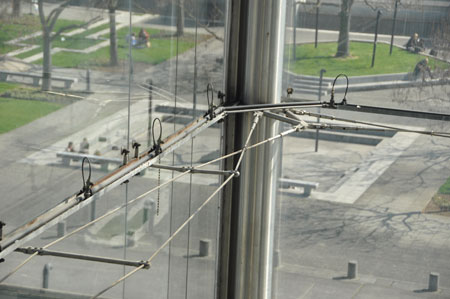 |
The Serres in Paris were the first example of the use of tension systems to support glazing. In these systems it is extremely important to allow for movement of the glass. In this case a 10 degree rotation is permitted through the use of a ball type connection. |
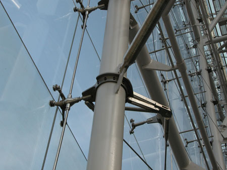 |
The use of spider connectors has increased through the years. Here at the Rose Center insulated glass panels called Pilkington Planar have been used. These require that the holes are drilled prior to tempering of the glass. |
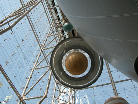 |
The Rose Center uses a cable truss system that spans from vertical tubular truss to vertical tubular truss, across the face of the glass, to resist the wind loads. This gives a high degree of transparency. |
 |
The Newseum uses a parallel cable system across the width of its large structural glass facade. The tolerances are very tight, but adjustment is also necessary between the parts. |