Steel Framing
Understanding Framing
Member to Member Connections. The connection of one member to another builds upon the basic principles in splices - lap joints and butt joints. Where direct transfer of forces through the connection is important, the primary steel is kept in line. All of the more innovative connections are really just variations on the basic types. Member to member connections must also consider constructability and the programmatic requirements of the building. Assemblages that are either brought to site or sub-assembled on site prior to erection, cannot exceed the capacity of the crane(s) for both weight and reach. It is easier and faster if members are connected via bolting on site as the ironworkers can insert a few temporary bolts as the pieces are erected allowing for the removal of the crane. Crane time is expensive and limited so the ability to detach the crane quickly is important. Where site connections must be welded, temporary bolted tabs are often used to secure the pieces in place to allow for the detachment of the crane and to make the location for the welding suitable for the job. Some framing techniques will use "seated connections" so that members rest on either a permanent or temporary "seat", making final connections easier to do.
Beam to Beam/Girder Connections
 |
 |
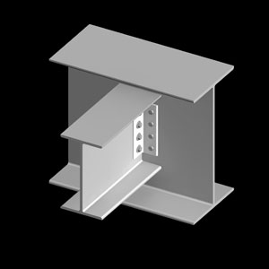
Coped connection. Here the top flange of the beam is cut away so that the top edges can align. Bolted angles are used to connect the webs of the wide flange sections together. |
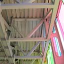
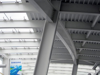
For this detail both the top and bottom flanges have been coped. It was important for the aesthetics of this large sun trellis to have both the top and bottom faces level. The smaller intermediate elements are much shallower so align only with the top edge. |
 |
 |
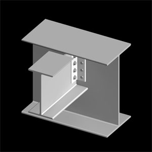
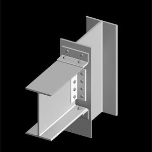
Framed connection.Where the beam frames into the web of the girder. This is a simple connection that is often used in structural steel framing where it is not necessary to allow for a floor system to sit on top of the beams. |
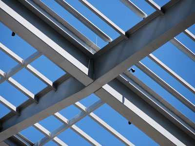
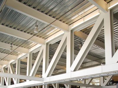
The beams that support the floor decking for this building simply frame into the top flange of this truss. There has been no adjustment of the height of the beam to suit the truss. In this case the truss is fabricated using wide flange sections, making it look very clean from the side view. |
 |
 |
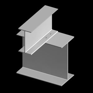
Simple Connection. Where the smaller beam sits on top of the larger member. This is easy to construct but uses up a lot of height that might not always be possible in tall buildings where floor to floor heights must be economized. The lower beam/girder provides a seat during erection. |
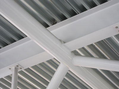
Although the wide flange beam that sits on top of the round HSS member has been modified, the intent of this connection is that of layering. The beam member is allowed to sit "on top" of the HSS member. Cutting into the beam and adding the curved plate to create the opportunity to weld the members together is quite innovative. It likely also made for easier fabrication and erection of the components. |
Beam to Column Connections
 |
 |
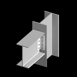
Simple framed connection.Angles are attached to the web of the beam and bolted to the flange of the column. You can also bolt to the web of the column, but be sure to allow room for the ironworker to access the bolts for tightening. |
These curved beams frame into the web of the tilted columns. The web of the beam is fixed to the web of the column through the use of a pair of steel angles. The depth of the column is adequate to permit the ironworkers to complete the bolting of the connection. Access for bolting is important when detailing connections. |
 |
 |
Seated connection. Although not designed to be moment resisting, the angle seat does provide for additional stiffness and a resting place for the beam during the erection process. |
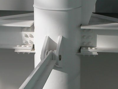
The connections on either side of the round column are seated connections. In this case instead of angles, plates have been welded to the column to provide both seat and some reinforcement. |
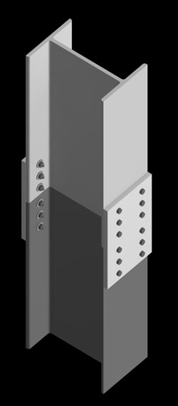
Column to Column Connections
For buildings that are over a storey in height, columns will require splicing. The taller the structure the greater the cumulative loads experienced at the lower floors, in contrast to the lighter loads at the roof level. This will mean that the column size will tend to decrease as you go up the building. There will be instances where two adjoining column lifts will be identical in size (outside dimensions and plate thicknesses). There will be instances where the dimensions might match but the plate thickness will be smaller on the upper column. And there will be instances where the alignment between the two columns is so different that an interstitial plate will be required to ensure proper load transfer through the connection and avoid load concentrations.
 |
 |
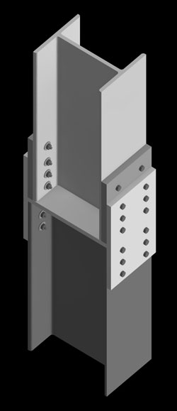 |
This illustrates a condition for two columns that are the same size. There is complete alignment of the two columns for an even transfer of load. The ends are machined for proper load transfer. The attaching plates arrive on the job site welded to the lower column. The plates at the sides are bolted on to attach the two column sections together. |
This illustrates a condition for two columns that are the same size. There is complete alignment of the two columns for an even transfer of load. The ends are machined for proper load transfer. The attaching plates arrive on the job site bolted to the lower column. The plates at the sides are bolted on to attach the two column sections together. |
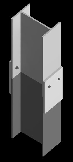
This illustrates a condition for two columns that are not the same size. This often happens in buildings as the columns on the lower floors need to take more load and so are larger. Here an intermediate plate transfers the load from column to column (the flanges do not align). Additional plates are used on the sides at the flanges as permanent shims to allow the most exterior plate to align. |